


PRODUCT SHOW
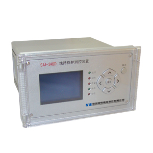
SAI-248D motor protection and control devices
1 . Function Deployment
Protection
Function Model SAI-238DC SAI-238DD
Three- phase overcurrent ЎМ ЎМ
Sec negative sequence overcurrent protection ЎМ ЎМ
Overvoltage protection ЎМ ЎМ alarm or trip
Low-voltage protection ЎМ ЎМ
Motor overheating protection ЎМ ЎМ
Small current zero-sequence alarms and trip protection ЎМ
Zero sequence overcurrent protection ЎМ alarm and trip
Non-power protection ЎМ ЎМ
2 . Description
2.1 start-up time (Tstart)
Means for measuring motor starting time Tstart method : When the maximum phase current of the motor from zero mutation move 10% Ie start counting until after excessive peak starting current drops to 120% Ie when the last date, is called the Tstart. (Ie is the motor rated current ) , motor starting time is too long will cause the rotor to overheat, when the starting time than the actual measurement device tuning allows starting time Tstart, protective action on the trip . Determine its start time shown in Figure 5.1 .
2.2 Three- white overcurrent
Device set definite time three sections alternating current protection. Equivalent speed off paragraphs ўс, current starting current escaped by tuning down automatically after the completion of half of the motor starter . That would effectively escape the huge start-up current of the motor, and can guarantee to provide preparedness severe overload caused by the normal starting motor stall protection . Action time T1 can tuning circuit breakers for motor control tuning time is usually shorter , and time spent tuning the motor contactor control generally longer, choose the setting of 0.3 seconds , the section mainly provides short circuit protection for the motor .
ўт and ўу segment segment segment is definite time overcurrent automatically put into the motor after startup is completed , the section can also be based on the current startup current or locked rotor current setting , the main motor starts running too long and stall protection. Cast back control setpoint value means:
0 : Exit 1 : Inputs
Overcurrent protection with a soft white plate and cast back control value , only the soft plate and cast back into the control values are given , the corresponding stages before investment.
2.3 Negative sequence overcurrent protection
The main negative sequence current protection for a variety of non-ground asymmetry fault , a larger negative sequence current and the negative sequence current in the rotor will
Produced twice the frequency of the current, additional heating of the rotor greatly increased , endangering the safe operation of the motor. Cast back control setpoint value means:
0 : Exit 1 : Inputs
Device set two definite time negative sequence overcurrent protection, phase protection segment ўс be used , ўт section can be used as an imbalance protection. Where negative sequence overcurrent ўт segment can be cast back control by setting I22nf select cast trip or alarm , while I2fsx select the paragraph definite time or inverse time characteristic control word value by inverse time
According to the International Electrotechnical Commission standards (IEC255-4) and the British Standard Specification (BS142.1966) of the regulations, the device uses its standard inverse characteristic equation extremely inverse characteristic equation (extreme IDMT.):
Ip is the current reference value , whichever is the negative sequence overcurrent ўт segment setpoint I22; time constant , take the negative sequence time overcurrent stage ўт value tI22.
Negative sequence overcurrent protection features soft cast back plate and the control value , only the soft plate and cast back into the control values are given , the corresponding stages before investment.
2.4 zero sequence overcurrent protection alarm and trip settings of the device zero sequence overcurrent protection alarm and trip , mainly for the user and low resistance grounding system settings . Back control of its investment value Ionf value means:
0 : Exit 1 to 2: inputs - 1: Alarm 1: Trip
Zero sequence overcurrent trip protection features soft plate, only the soft plate and cast back into the control values are given , the trip was put into protection ; zero sequence overcurrent alarm input control word can only generate an alarm event .
2.5 small current zero- sequence overcurrent protection alarm and trip
This device is set to zero sequence overcurrent protection alarm and trip , mainly for non-grounded system and user settings . Can be cast back control value (Ioxnf) setting for the alarm and trip . Cast back control setpoint value means:
0 : Exit 1 to 2: inputs - 1: Alarm , 2 : Trip
Zero sequence overcurrent trip protection features soft plate, only the soft plate and cast back into the control values are given , the corresponding trip protection only cast
Income ; zero sequence overcurrent alarm input control word can only generate an alarm event .
2.6 overheat protection principles
Considering the motor positive sequence , negative sequence current thermal effect generated by the load of the motor overheating caused by a variety of over- protection , but also as a motor short circuit , start-up time is too long , stall and other back-up protection.
Equivalent current Ieq to simulate the heating effect of the motor , namely:
Where : Ieq- equivalent current
I1- positive sequence current
I2- negative sequence current
K1- positive sequence current heat coefficient , the motor during startup K1 = 0.5, start the restoration is completed K1 = 1
K2- negative sequence current heat coefficient , K2 = 3 ~ 9, desirable K2 = 6 is given by the following formula based on the characteristic curve of the heating operation of the motor model , the motor running current time t and the equivalent Ieq between :
[(Ieq / Ie) 2 - (1.05) 2] * t ЎЭ ҰУ
Where ҰУ: motor thermal accumulation value , namely the thermal time constant tHT, this constant is provided by the electrical plant .
Send an alarm signal when the heat accumulated value reaches tHT Ёw Ka ( overheat alarm coefficient ) ; overheat alarm function can be given value by controlling HTBJnf invest or exit into the overheating alarm function , overheat protection , whether soft plate put in , all with alarm function .
When the heat accumulated value reaches tHT sent trip signal.
Control value HTnf invest or exit , meaning its value is as follows :
0 : Exit 1 : Trip
2.7 Overvoltage Protection
In the co- breaker bit case, the three -phase alternating voltage has a value greater than the over-voltage protection , longer than the setting time , the over-voltage protection . Over-voltage protection features cast back control value UHnf, values have the following meanings :
0 : Exit 1 : Alarm , 2: tripping.
Over-voltage protection features soft plate trip , only soft plate and cast back into the control values are given , the corresponding trip protection was put in ; over-voltage alarm input control word can only generate an alarm event .
2.8 Low Voltage Protection
The low- voltage protection device cast back control setpoint values ULnf meaning :
0 : Exit 1 : loss of pressure + low-voltage protection , 2 : Invalid , 3: pure low- voltage protection
Loss of pressure + low voltage protection conditions are:
1: The circuit breaker together bits
2: The three -phase voltage is less than the low-voltage protection setting
3: When U1 <0.15Un, Imax <0.02In or when U1> 0.15Un, U2 <8V.
Pure low- voltage protection conditions are:
1: The circuit breaker together bits
2: The three -phase voltage is less than the low-voltage protection value and greater than 0.15Un
2.9 Overload protection
Overload protection device cast back control setpoint values Igfhnf meaning :
0 : Exit 1 to 2: inputs - 1: Alarm , 2 : Trip
Overload trip protection features soft plate, pressure plate and throw only soft values are given back control inputs , the corresponding trip protection only cast
Income ; overload alarm input control word can only generate an alarm event .
2.10 Non- electrical protection
Set two non-power device protection , respectively, with a soft cast back plate and a control value , only the soft plate and cast back into the control values are given , the corresponding stages before investment.
After the non-electricity a contact closure , after tFDL1 delay, if FDL1nf = 1, then a trip command, and letters ; If FDL1nf = 2, only an alarm signal.
After the non-power 2 contact closure , after tFDL2 delay, if FDL2nf = 1, then a trip command, and letters ; If FDL2nf = 2, only an alarm signal.
Non-power protection plate with a soft , flexible plate only when the corresponding control inputs and set the correct word , the corresponding protection was put into .
Non-power protection function can be used as process interlock protection of the motor.
2.11 abnormal condition alarm system and locking function
2.11.1 bus PT break alarm
Meet any of the following one , issued by the delay device bus PT break alarm signal.
ўЕ positive sequence voltage U1 < when 0.15Un, any phase current > 0.04In
ўЖ negative sequence voltage U2> 8V.
2.11.2 Control loop break alarm
TWJ and HWJ same time is 1 or 0 , after the alarm delay .
3 . Device tuning
Including soft plate tuning device , the device settings and device parameters in three areas , see 3.1, 3.2 and 3.3 .
Tuning should follow the relevant regulations , the device has special requirements in the relevant notes. Device parameters without special needs , it is desirable default values listed in the table . No protection, it should control the value to 0 - exit.
3.1 Soft- plate tuning device
Model SAI-238DC SAI-238DD
Three sections of white over-current protection ЎМ ЎМ
Overload protection ЎМ ЎМ
Sec negative sequence overcurrent protection ЎМ ЎМ
Overvoltage protection ЎМ ЎМ
Low-voltage protection ЎМ ЎМ
Motor overheating protection ЎМ ЎМ
Small current zero-sequence protection ЎМ
ЎМ zero sequence overcurrent protection
Non-power protection ЎМ ЎМ
Note : Soft plate only two values: inputs, quit. When the device is shipped , soft plate are tuning to quit.
3.2 Device setting value
No. Name Symbol tuning range Remarks
A motor rated current Ie 2.1 ~ 10A
2 motor starting time Tqd 0.1 ~ 60S
3-phase
Between
Live
Flow
Insurance
Care segment segment ўс ўс phase overcurrent protection cast back control I1nf
4 white overcurrent stage ўс current value I1 0.5 ~ 100A
5 Section ўс phase overcurrent delay setting tI1 0.01 ~ 9.99S
Section 6 Section ўт ўт phase overcurrent protection cast back control I2nf 0 ~ 2
7 segment ўт phase overcurrent current value I2
Section 8 ўт white overcurrent delay setting tI2 0.1 ~ 9.99S
Section 9 ўу ўу phase overcurrent protection section cast back control I3nf
10 white overcurrent stage ўу current value I3 0.5 ~ 100A
ўу overcurrent delay setting section 11 white tI3 0.1 ~ 60S
12 Inverse Inverse time protection features alternate control word Ifsx 0 ~ 3
13 white inverse time protection current reference value Ii 0.5 ~ 100A
14 white inverse time protection time constant tIi 0.1 ~ 99.99S
15 public value PT break detection cast back control PTDXbs
16 low-pressure phase overcurrent closed lock value ULbs 2 ~ 120V
17 Overload
Overload protection alarm or trip protection cast back control Igfhnf 0 ~ 2 Note 1
18 overload current value Igfh 0.5 ~ 100A
19 overload delay setting tIgfh 0.1 ~ 99.99S
20 Negative sequence over
Stream protection zones of phase ўс ўс negative sequence overcurrent stage cast back control I21nf
21 white negative sequence overcurrent stages ўс current value I21 0.5 ~ 100A
22 white negative sequence overcurrent stages ўс delay setting tI21 0.1 ~ 99.99S
23 Section ўт ўт and white negative sequence overcurrent paragraph cast back control I22nf 0 ~ 2 Note 1
24 white negative sequence overcurrent ўт segment current value I22 0.5 ~ 100A
25 white negative sequence overcurrent ўт segment delay value tI22 0.1 ~ 99.99S
26 white negative sequence overcurrent II segment Inverse Control I2fsx
27 small current
Zero sequence over
Flow zero sequence overcurrent protection alarm or trip cast back control Ixonf 0 ~ 2 Note 1
28 zero-sequence current value Ixo 0.005 ~ 0.999A
29 zero-sequence delay setting tIxo 0.01 ~ 9.99S
30 Overvoltage
Protection of over-voltage protection alarm or tripping cast back control UHnf 0 ~ 2 Note 1
31 Over-voltage line voltage setpoint VUH 20 ~ 150V
32 Overvoltage Delay setting tUH 0.1 ~ 99.99S
33 low voltage protection Low voltage protection trip setpoint ULnf 0 ~ 3 Note 3
34 low- voltage line voltage setpoint VUL 10 ~ 100V
35 Low-voltage protection delay setting tUL 0.1 ~ 99.99S
36 low-voltage current closed lock value ILbs 0 ~ 10A
37 Overheat protection Overheat protection cast back control HTnf
38 thermal time constant tHT 500 ~ 30000S
39 coefficients of thermal effect of negative sequence current K2 3 ~ 9
Cooling time of 40 multiple nCL 1 ~ 4
41 overheat alarm cast back control HTBJnf
42 overheat alarm coefficient Ka 30 ~ 99%
43 non-power
Protection of non-electricity a trip or alarm control FDL1nf 0 ~ 2 Note 2
44 non-power a delay value tFDL1 0.01 ~ 99.99S
45 non-power 2 trip or alarm control FDL2nf 0 ~ 2 Note 2
46 non-power two delay setting tFDL2 0.01 ~ 99.99S
Note:
1 value meaning Igfhnf, I22nf, Ionf, Ixonf and UHnf control word as follows :
0 : Exit 1 to 2: inputs - 1: Alarm 2 : Trip
(2) the value and meaning of FDL1nf FDL1nf control word as follows :
0 : Exit 1 to 2: inputs - 1: Trip 2 : Alarm
3 Value Meaning VUL control word as follows:
0 : Exit 1 to 3 : inputs - 1: The loss of pressure + low voltage 2 : Invalid 3 : pure low-voltage
3 device parameter tuning
No. Name Symbol Range step defaults
A device -level management device mailing address ADDR 1 ~ 110 1 1
2 operation of the device password is PASSWORD 0 ~ 99 1 00
3 baud CAN baud rate setting BTL 0 ~ 9 1 9
4 AC rated CT primary current rating of the amount Sec.IN 0 ~ 65535A 1A
5 PT primary current rating Sec.UN 0 ~ 999.9KV 1 KV
4 . Protection Principle wiring diagram
