


PRODUCT SHOW
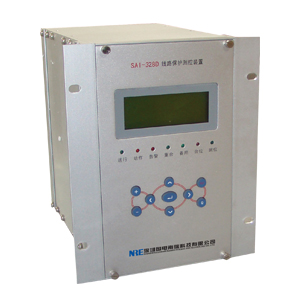
SAI-328D digital capacitor protection and control devices
I. Overview
SAI-328D is for 66kV and below the neutral point arc suppression coil grounding or shunt capacitor protection and control devices are not grounded in the installation of low voltage systems can be installed locally on the switch cabinet . For single Y, double Y, △ -shaped junction capacitor bank .
SAI-328D is a current-voltage protection and unbalanced voltage protection device protects the capacitor sets the basic configuration ; SAI-328D is a current-voltage protection and unbalanced current protection device to protect the capacitor sets the basic configuration.
Protection configuration:
● Two-stage overcurrent and white
● Two-stage zero sequence overcurrent protection
● current protection definite time , inverse time optional
● zero sequence protection definite time , inverse time optional
● undervoltage protection
● Overvoltage Protection
● phase imbalance protection (SAI-328D-1 corresponds to the voltage unbalance , SAI-328D-2 corresponds to the current imbalance )
● negative sequence overcurrent protection
● Since switching protection
● PT break automatically detect
● small current grounding line selection function
Control Function Deployment
● 11 road open into the strong electric remote signal acquisition
● device power failure alarm , emergency signal device , the device alarm signal
● breaker remote switching , grounding jump
● analog telemetry : Ia, Ib, Ic, Ua, Ub, Uc, Q
● 2 -way pulse input
● 1 -way GPS time
Second, the principle that the protection of
2.1 , overcurrent elements
Real-time computing device and overcurrent discrimination Sec .
Sec apparatus when performing an overcurrent determination , the logical consistency determination section , the operating conditions were as follows:
1) I> In; Idn segment current value of n , I is the phase current
2) T> Tn; Tn segment delay value is n
Its logic is as follows :
In the section where the current set value n , Ia, b, c of the phase current
2.2 , zero-sequence overcurrent elements
Zero-sequence overcurrent elements of implementation and overcurrent same basic components, exports trip when the following conditions :
1) 3I0> I0n; I0n: Ground segment value N
2) T> T0n; T0n: Ground segment delay value N
2.3 , inverse time element
Inverse time protection components and protection element is the action lines in the current size of the protected natural fit through translational motion curves, can easily achieve full cooperation. Common analytic inverse characteristic about divided into three categories , namely, the standard inverse, very inverse , extremely inverse , inverse-time characteristics of the device by the setting value in inverse time index tuning . Each inverse characteristic formula is as follows :
a. general inverse time ( setting range is 0.007 to 0.14 )
b. Very inverse ( setting range is 0.675 to 13.5 )
c. extremely inverse ( tuning range is 4 to 80 )
Where : tp is the time factor , the range of ( 0.05 to 1 )
Ip is the current reference value
I is the fault current
t for the trip time
Note: The setting value multiplied by the value of inverse time as part of the molecules in the above expression , in seconds .
Its logic is as follows :
This device phase current and zero sequence currents are given with inverse time protection, through the relevant bit is set to select the control word definite time or inverse time mode . When you select inverse time mode automatically exits definite time overcurrent and Section II Section II of zero flow components, functions and white plate current and zero sequence current section II II segment were changed to alternate current and zero sequence current Inverse Inverse function vote back plate .
2.4 , undervoltage protection element
Under-voltage capacitor banks in order to protect components from damage and settings.
Undervoltage element operating conditions :
1 ) three line voltages are below the undervoltage setting Uqdy;
2 ) The three-phase current is less than the line undervoltage lockout current setting Ibs;
3 ) the delay time to ;
4 ) control circuit breaker and no disconnection signal together bit .
Its logic is as follows :
Which , Iabc of phase currents Ia and Ib and Ic, Ibs as undervoltage lockout current value , Uqdy low pressure setpoint
2.5 Over-voltage components
Over-voltage capacitor bank component but also to protect against damage and settings.
When the following conditions are met , over-voltage component actions:
A ) any of the three line voltage to a voltage higher than the overvoltage setting value ;
2 ) the circuit breaker in the aggregate bit ;
3 ) the delay time to .
Its logic is as follows :
Which Ugdy value for the overpressure
2.6 , unbalanced components
Are used to prevent an imbalance within the capacitor element failure, the operation conditions were as follows :
1 ) Enter the amount of any single-phase unbalanced (single -phase ) or three-phase unbalanced unbalanced input in setting the value of a ( three-phase ) greater ;
2 ) the circuit breaker in the aggregate bit ;
3 ) the delay time to .
Description : SAI-328D input voltage unbalance , SAI-328D input current imbalance
When the SAI-328D unbalanced analog input only one time , either on the terminal phase imbalance in the access can be a phase .
Its action logic is as follows :
2.7 , since the switching function
When not using the integrated automation and reactive power regulating device ( such as VQC), the user can choose which functions under the circumstances.
Automatic removal of conditions :
1 ) three line voltage is greater than any one since switching overvoltage value ;
2 ) unprotected action blocking signal ;
3 ) breaker in close position ;
4 ) Since switching control plate and put into words ;
5 ) the delay time to .
Its action logic is as follows :
Automatic input conditions :
1 ) three line voltage is less than switching from low- value and greater than 64V;
2 ) unprotected action blocking signal ;
3 ) the circuit breaker in the sub- bit ;
4) TWJ for 5 minutes ;
5 ) Since switching control plate and put into words ;
6 ) the delay time to .
Its action logic is as follows :
Note:
1 Since switching action time suggested more than two seconds .
(2) To prevent accidental self- cast capacitor at fault , hand jump, jump or throw a protective action lockout vote fashionable cut , the protection device automatically exits from the cast cut soft platen. At this alternate exit a junction (4x13-4x14) should be fed back into the incision access lockout vote (2x2).
2.8 PT disconnection detection function with SAI-318D.
PT disconnection detection function can be cast back through the control word.
2.9 Data Record
Function with SAI-318D.
Analog recording can increase BPHA, BPHB, BPHC.
2.10 , remote telemetry, remote control
Function with SAI-318D.
Third, tuning and event information devices
3.1 , setting the value of a list and description of
No. Name Symbol Range Unit value Remarks
A control word a KG1 0000 ~ FFFF no see control word description
2 control word two KG2 0000 ~ FFFF no spare
3 Current section Ⅰ I1 0.2 ~ 100.0 A
4 Current Ⅱ paragraph I2 0.2 ~ 100.0 A
5 Current section Ⅰ time T1 0.0 ~ 20.00 S
6 Current Ⅱ period of time T2 0.1 ~ 20.00 S
Section 7 Ⅰ zero-sequence current I01 0.1 ~ 20.0 A
8 Section Ⅱ zero sequence current I02 0.1 ~ 20.0 A
9 zero-sequence segment Ⅰ time T01 0.0 ~ 20.00 S
10 zero-sequence segments Ⅱ time T02 0.1 ~ 20.00 S
11 Current Inverse benchmark IP 0.2 ~ 100.0 A
12 Current inverse time TP 0.005 ~ 127 S
13 zero-sequence Inverse benchmark IP0 0.1 ~ 20.0 A
14 zero-sequence inverse time TP0 0.005 ~ 127 S
15 Inverse Index Exp 0.01 ~ 10.0 no 0.02,1 , or 2
16 over-voltage setpoint Ugdy 30 ~ 120.0 V
17 over-voltage action time Tgdy 0.0 ~ 100.0 S
18 under voltage setpoint Uqdy 10 ~ 100.0 V
19 under voltage action time Tqdy 0.0 ~ 100.0 S
20 undervoltage lockout current Ibs 0.2 ~ 100.0 A
21 unbalanced voltage BPH 0.5 ~ 100.0 V *** or unbalanced current 0.1 ~ 20.0A
22 unbalanced operation time Tbph 0.0 ~ 20.0 S
23 since switching overvoltage value Uzq 30 ~ 120.0 V
24 switching from low- value Uzt 30 ~ 120.0 V
25 self- cast action time Tzt 0.0 ~ 60.0 S
26 self- cutting action time Tzq 0.0 ~ 60.0 S
27 measuring CT ratio (KA / A) CT 0.01 ~ 10.0 without a current / ( secondary current * 1000 )
28 PT ratio (KV / V) PT 0.01 ~ 10.0 without a voltage / ( secondary voltage * 1000 )
Control word 1 Definition:
Meaning Bit 0 is set to 1 when the meaning set
Sum 15 Sum self-test inputs to exit the self-test
14 CT rated current of 1A CT rated current of 5A
13 ways to protect Select Inverse time protection mode selection rules
12 Since switching functions into exit from switching function
1 to 11 Reserved Reserved
0 overvoltage take alternate line voltage gap
3.2 , soft list and description of the platen
Corresponding function name plate
Current segment segment Ⅰ Ⅰ current protection cast back
Current Ⅱ Ⅱ segment segment current protection cast back
Segment zero sequence zero-sequence segment Ⅰ Ⅰ protection cast back
Zero sequence zero-sequence segment Ⅱ Ⅱ segment protection cast back
Unbalance unbalance protection cast back
Overvoltage overvoltage protection cast back
Undervoltage undervoltage protection features cast back
Alternate alternate function cast back
Alternate alternate function cast back
Since switching from switching feature cast back
