


PRODUCT SHOW
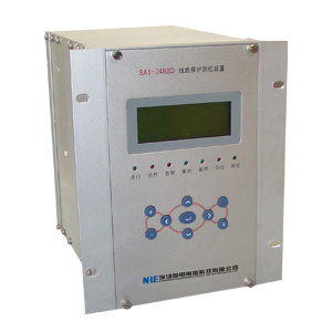
SAI-3482D digital synchronous motor backup protection device
I. Overview
SAI-3482D digital motor backup protection device for 3-10KV voltage class high-voltage synchronous motor protection and control can be locally installed in the switch cabinet .
Protection configuration
�� current protection
�� Over Current Protection
�� zero sequence ground fault protection
�� negative sequence overcurrent protection
�� overheating protection
�� Low Voltage Protection
�� Low Week protection
�� Asynchronous impact protection
�� loss protection
�� step protection
�� non-power protection
Control Function Deployment
�� 11 road open into the strong electric remote signal acquisition
�� device power failure alarm , emergency signal device , the device alarm signal
�� breaker remote switching
�� analog telemetry : Ia, Ib ( optional , must specify when ordering ), Ic, Ua, Ub, Uc, P, Q, COS��
�� 2 -way pulse input
�� 1 -way GPS time
Second, the principle that the protection of
2.1 Start-up time element
Means for measuring motor starting time Tstart method : When the maximum phase current of the motor from zero mutation move 10% Ie start counting until after excessive peak starting current drops to 120% Ie when the last date, is called the Tstart. (Ie is the motor rated current. ) Motor starting time is too long will cause the rotor to overheat, start-up time when the actual measurement device exceeds the allowable start time setting Tstart, protective action on the trip .
2.2 , overheating protection
Considering the motor is positive, the thermal effect generated by the negative sequence current , the motor load caused by superheating of various protection , short-circuit and as a motor start-up time is too long, such as back- stall . Used to simulate the equivalent current Ieq ¬ heating effect of the motor, namely:
Where : Ieq- equivalent current
I1- positive sequence current
I2- negative sequence current
K1- positive sequence current heat coefficient , the motor during startup K1 = 0.5, start the restoration is completed K1 = 1
K2- negative sequence current heat coefficient , K2 = 3 ~ 10, desirable K2 = 6
According to the heating characteristic curve of the motor model , the operation of the motor operating current and the equivalent time t between Ieq is given by the following equation :
Where: Ip- load current before overload if the overload is cold front , then Ip = 0
I �� - starting current , that protection is not required for operation of the provisions of the current limit
the time constant ��- reflecting capacity of the motor overload
This criterion is fully considered the motor stator and thermal process state before the load is too hot . Device to indicate the heat content of the motor is proportional to the square of the heat , the heat content of the stator current , by conversion, into its dimensionless motor overload capacity reflects the time constant ��. When the heat content value reaches ��, the device is tripped . When the heat content of Ka �� ��, hair overheat alarm signal , which , Ka is a warning factor , which ranges : thermal alarm can be set to heat accumulation whole trip ( 60 to 99.9 ) % , the device provides real-time heat accumulation value display , alarm indication lights and signal contacts output.
According to the principle of the motor can be started twice in a row , each time you start the trip 50% of its value should not be greater than the heat accumulation , so when the heat accumulation value drops below 50 percent , closing latching device contacts to return. After tripping overtemperature protection , thermal memory device startup , output contacts have been closed until the heat accumulation value drops below 50 percent , closing latching contacts overheating return , then the motor can be restarted. When an emergency situation requiring immediate start, thermal reversion operation of the device .
Starting current I �� rated current Ie can be 1.05 to 1.15 times the setting .
Thermal time constant �� provided by the electrical plant , if the manufacturer does not provide , according to the estimate of one of the following methods :
�� If manufacturers provide thermal limit curve or a group of motor load capacity over the data , then calculated as ��:
After obtaining a set of �� small value .
�� if known Stall current I and allowed to stall time t, but also by the following formula to estimate ��:
�� calculated as ��:
Where : ��e rated motor temperature , K is the starting current multiples , ��0 is the temperature rise of the motor startup , Tstart as motor starting time .
2.3 Asynchronous impact protection
Does not allow for large -capacity synchronous motor asynchronous shocks can be reverse power components or asynchronous low-power components as impact protection . Low power protection applies to no other on the bus load, low- power protection by the switch contacts latching position, the latch asynchronous impact protection when TV break . Reverse power components and low power devices from the " Options " control word " asynchronous impact protection " option. Impact protection can be asynchronous action in another whole step or trip circuit .
2.4 , loss protection
Asynchronous boundary Magnetoimpedance round loss as the main criterion , plus the negative sequence voltage lockout constitute loss protection synchronous motor , the negative sequence voltage lockout may be " cast back plate " control word " negative sequence magnetic latch failure " cast back . During motor starting and TV break blocking loss protection , loss protection can be automatically put in the motor starter is completed , but also by the platen or external contact control inputs, the use of a plate or external contact control inputs must be " Options " control word "loss magnetic input methods " selected "Manual ."
2.5 out of step protection
To detect synchronous motor power factor angle based criterion , while adding its static stability boundary curves and low current lockout constitute step protection of synchronous motor , static stability boundary discrimination and low current blocking function can be controlled by the " cast back plate " respectively word " static stability criterion out of step " and "low flow atresia out of step " to cast back . Atresia loss in motor starting and protection of PT disconnection step , step protection can be automatically put in the motor starter is completed , but also by the platen or external contact control inputs, the use of a plate or external contact control inputs must be " Options " control word " way out of step into " selected "Manual ." Action step protection can step in and then the whole circuit or tripping.
2.6 , instantaneous protection
As the main motor winding and lead phase short circuit protection when . When the machine side ( supply side ) maximum phase current value is greater than the current setting , protection instantaneous action on the trip .
Instantaneous protection current setting speed including motor when starting off current value Isdq and running speed off current value Isd, Isdq can escape the motor at rated load maximum starting current to tuning, namely : Isdq = kk �� Iqd ( where : kk- reliability coefficient , taken as 1.3, Iqd- largest motor starting current ); Isd can escape outside the area when a short circuit fault current flowing through the motor to the maximum setting , the general desirability of Isdq a half, Isd = 0.5 �� Isdq.
When the motor starts, quick-break current value is automatically set to Isdq, when the motor starters finished, quick-break current value is automatically set to Isd, so that we can avoid starting process due to excessive starting current caused by malfunction, while also can guarantee the normal operation of the protection with high sensitivity. Interruption Protection has a delay when the delay setting is 0 , that is instantaneous action . If the motor using fuses - high voltage contactor (FC) loop control , the protection may be delayed trip to escape the fuse blown set time .
2.7 , overload protection
Overload protection set Sec delay t1 and t2, when the maximum phase current is greater than the set value , by the delay t1 overload alarm signal sent by the delay t2 action on the trip .
Overload protection automatically exit when the motor starts automatically put into the starting end .
2.8 , stall protection
When the motor rotor is at a standstill ( slip S = 1), the current will increase sharply and cause the motor to burn accident. Motor speed switching signals can be introduced and together constitute the positive sequence current blocking protection , which can motor speed switch signal " cast back plate " control word " speed switch contacts " cast back , the speed switch contacts from the terminal X4: 5 access . Stall protection but also as a reserve short-circuit .
Stall protection automatically exit when the motor starts automatically put into the starting end . If the process occurs in the motor starting stall, long protection will start the action , although the operating time may be greater than the allowable stall time , but considering the stall before the motor is cooled state, allowing appropriate to extend the trip time .
2.9 , ground protection
Zero sequence current generally get special zero-sequence current transformer , if equipped with three-phase CT, the three-phase currents can also be obtained . Device uses the following three criterion for users to choose :
Criterion 1 ( zero sequence current criterion ) : Suitable for ground fault current larger systems .
�� 3I0> I0zd;
�� time to delay .
Zero sequence fundamental current zero-sequence current value can be escaped outside of single phase motor tuning . If zero sequence CT ratio is not clear, in the zero-sequence CT primary current pass into the ground to monitor the measured values can be used as the secondary side of the setting value .
Criterion 2 ( zero sequence directional criterion ) : For ungrounded or with high resistance grounding system in �p .
�� start using zero-sequence current , ie 3I0> I0zd after 100ms delay confirmation ;
�� meet 90 �� \ u65308Xarg (3U 0 �u 3 I 0) <180 �� \ u12290X
�� Time Delay to .
Criterion 3 ( zero sequence active criterion ) : For the neutral point arc suppression coil grounding system.
�� The zero-sequence voltage start , that 3U0> U0zd, after 1s delay confirmation ;
�� to the fundamental zero -sequence voltage 3U0 bus calculated based on the measured zero- sequence active component P0, P0 if �� �� �� P0zd ground fault occurs , if P0 �� �� <(0.2 ~ 0.3) P0zd is ungrounded .
�� Time Delay to .
Among them, the absolute zero sequence �� �� P0 meritorious ; P0zd = 0.5 �� PL, PL for the Petersen coil power loss . Users can " Options " control word "ground protection criterion " criterion to select a criterion for protection . To improve the accuracy of ground fault protection , the device uses a high-precision zero-sequence current transformer, zero sequence TA device rated current of 1A or less , do not enter the large current for a long time in order to avoid damage to the inverter .
2.10 , negative sequence overcurrent
The main negative sequence current protection for a variety of non-ground asymmetry fault , such as: a phase motor phase failure occurred when the size of the negative sequence component failure due to pre- load rate varies , the load rate is greater than 0.7, the sound can cause excessive phase current, and therefore can not effectively protect the asymmetric general protection fault . When the motor is running , due to the asymmetric power supply , there is always a certain degree of negative sequence current, which will not exceed 30% Is, negative sequence protection tuning should be able to escape this negative sequence current , ie 0.3Is tuning . Operation time characteristics selectable two -time characteristics , select definite time and inverse, extremely inverse action equation:
Where : tp is the time factor , the range of ( 0.05 to 1 )
Ip is the negative sequence current setting
I fault negative sequence current
t for the trip time
Note: The setting value multiplied by the value of inverse time as part of the molecules in the above expression , in seconds , tuning range ( 0.4 to 80 ) .
2.11 , low voltage protection
When the power supply bus voltage to reduce short-term or short interruptions when the power supply voltage to prevent the motor from starting severely reduced , low- voltage protection shall be installed in a number of minor motor or without a motor from starting . When the voltage between phases were lower tuning voltage protection by tuning delay action . Low voltage setpoint can escape when the minimum voltage motor starting tuning . Low-voltage lockout protection may be no flow �p TWJ break blocking position blocking and PT , respectively, through the " cast back plate " control word " no flow lockout Low ( protection ) ", " jump -bit low-voltage lockout (Protection ) " and " PT break blocking ( related protection ) " cast back . To prevent operation when the TV spot low voltage protection circuit malfunction , low-voltage protection can be cast back panel switch on the device appropriated exit position.
2.12 , over- voltage protection
Power overvoltage causes iron loss and copper loss is increased, the temperature rise of the motor .
When the voltage is greater than alternate tuning voltage protection by tuning delay action .
2.13 , reverse power protection
If the motor is sent to a short circuit near the inverse power may cause harm to the system shall be installed reverse power protection .
When the device detects the motor absorbed active power is negative , by tuning delay action .
Reverse power protection can be broken by TV atresia , through the " cast back plate " control word "TV break blocking ( related protection ) " cast back .
2.14 , low cycle protection
When the frequency is below the set value , the protection by setting the delay action . Low cycle protected by a " cast back plate " control word determines whether through low-voltage lockout and slip atresia. When the motor is started or not running , low cycle protection automatically exit .
2.15 , thermal overload lockout ( close circuit )
When the motor to stop the run , if this is greater than the heat content of the motor kb �� \ u964X, the latch closing circuit , BSJ action latching relay that disconnected closing the loop in order to prevent re- start within a short time and cause motor overheating . When the heat content of less than kb �� \ u964X, automatically lifting the latch . Which , kb is latching coefficient , which ranges : (Ie / I ��) 2 <kb <1.
Continuous -click the "Return" key , the heat content is automatically cleared , the supply and demand for emergency use when starting and testing.
2.16 , consecutive start atresia ( close circuit )
After the motor starting device lockout began closing the loop , that BSJ action latching relay circuit disconnect switch on until the delay setting up , in order to prevent the time interval between successive start causing no serious motor overheating .
If the starting current is greater than 112% Ie, in the starting current drops to 112% Ie when the latch closing loop .
If the starting current is less than 112% Ie, the allowable start time is reached when the lockout Tstart closing loop .
If the start-up process abnormally aborted ( eg protection action , hand jump ) , then abort time close in the loop .
2.17 , non-power protection
This device must match the external light control relay . Come from non-electric motor body contact, by converting light control relay 24V signal , the switch output signal to the device 's input terminals. After receiving the non-power signal , trip or not is determined by the soft platen. Such as soft platen exit , only for ordinary credit away , otherwise it will jump all the switches accordingly . After the device trips, event logging , and MMI will be recorded by the computer to upload to the background .
2.18 Data Records
Function with SAI-318D.
2.19 , remote telemetry, remote control
Function with SAI-318D.
Third, tuning and event information devices
3.1 , setting the value of a list and description of
No. setting content type value range name
Setting switch 1 No. 0 ~ 9 value Code
Rated current 2 Ie 0.4 ~ 5 Rated Current (A)
Interruption Protection 3 * Isdq (1 ~ 20) Ie full voltage starting speed to determine the value of (A)
4 * Isdqj (1 ~ 20) Ie voltage starting speed to determine the value of (A)
5 Isd (1 ~ 20) Ie operating speed determined value (A)
6 T 0 ~ 1 action delay (S)
Overload protection 7 Ig (1 ~ 4) Ie overload value (A)
8 T1 1 ~ 1000 overload alarm delay (S)
9 T2 1 ~ 1000 overload action delay (S)
Thermal overload protection 10 I �� (1.05 ~ 1.15) Ie starting current (A)
11 �� 60 ~ 3000 time constant (S)
12 Ka (Ie / I ��) 2 ~ 0.999 coefficient overheat alarm
13 Kb (Ie / I ��) 2 ~ 0.999 coefficient overheat lockout
14 K2 3 ~ 10 negative-sequence current effect coefficient
Stall protection 15 I1 (1 ~ 10) Ie positive sequence current (A)
16 T 1 ~ 60 action delay (S)
Long start protection 17 Tstart 10 ~ 100 allows the start time (S)
Negative sequence inverse time overcurrent 18 I2q (0.04 ~ 1) Ie negative sequence starting current (A)
19 T3q 0.1 ~ 20 I2 = 3I2q allowable time (S)
Negative Sequence Time Overcurrent 20 I2q �� (0.08 ~ 1) Ie negative sequence segment �� value (A)
21 T1 0.5 ~ 12 negative-sequence segment �� delay (S)
22 I2q �� (0.08 ~ 1) Ie negative sequence �� segment value (A)
23 T2 0.5 ~ 12 negative sequence �� segment delay (S)
Ground protection 24 3I0 0.003 ~ 2 zero sequence starting current (A)
25 3U0 1 ~ 50 zero-sequence start voltage (V)
26 P0zd 0.2 ~ 32000 Zero sequence active setpoint (W)
27 T 0.2 ~ 10 action delay (S)
Low-voltage protection 28 Ul (0.1 ~ 0.9) Ue low voltage value (V)
29 T 0.5 ~ 10 Low Voltage Delay (S)
Overvoltage protection 30 Ug (0.9 ~ 1.5) Ue overvoltage value (V)
31 T 0.5 ~ 10 Overvoltage Delay (S)
Low cycle protection 32 Fl 45 ~ 50 week low frequency value (Hz)
33 T 0.1 ~ 10 week low latency (S)
34 ��f / ��t 0.5 ~ 10 slip closed lock value (Hz / S)
35 Ul (0.1 ~ 0.9) Ue low pressure closed lock value (V)
Consecutive start close in 36 Tb 10 ~ 600 lockout time (S)
Asynchronous impact protection 37 Pzd (0 ~ 0.2) Pe fixed power (W)
38 T 0.1 ~ 10 action delay (S)
Loss protection 39 XA 10 ~ 100 lost Magnetoimpedance (��)
40 XB 10 ~ 100 lost Magnetoimpedance (��)
41 U2 1 ~ 10 atresia negative sequence voltage (V)
42 T 0.1 ~ 100 loss of field delay (S)
Step protection 43 ��qd 0 ~ 60 starting power factor angle (��)
44 Iqd (0.2 ~ 1) Ie low flow closure locking value (A)
45 Xd 10 ~ 100 synchronous reactance (��)
46 Xs 10 ~ 100 system reactance (��)
47 T 0.5 ~ 10 action delay (S)
Pulse of the 48 Kp 0 ~ 65535 active pulses / kWh
49 Kq 0 ~ 65535 Reactive pulses / kWh
Ratio tuning 50 Kct 0 ~ 9999 CT ratio ( primary / secondary )
51 Kpt 0 ~ 9999 PT ratio ( primary / secondary )
52 Kct0 0 ~ 9999 zero sequence CT ratio ( primary / secondary )
Mailing Address 53 Addr 0 ~ 240 decimal
Baud rate 54 RS485 0,1,2,3 0-4.8 1-9.6
2-19.2 3-38.4 (Kbps)
55 CAN 0,1,2,3
4,5,6,7 0-6.25 1-12.5 2-25
3-50 4-31.25 5-62.5
6-125 7-250 (Kbps)
3.2 , a list and description of the platen
No. Name of the control word value names tuning range
Total investment return an exit plate plate into / exit
2 Interruption Protection Enable / Disable
3 buck starting way into / exit
Section 4 overload alarm inputs / Exit
Section 5 load tripping over into / exit
6 Thermal overload protection input / exit
7 overheat alarm inputs / exit
8 overheating atresia ( closing ) into / exit
9 stall protection enabled / disabled
10 speed switch contact inputs / exit
11 long start protection enabled / disabled
12 Negative sequence overcurrent stage �� / Disarm
13 Negative sequence overcurrent �� segment into / exit
14 Inverse Negative sequence overcurrent input / exit
15 I2 �� 1.2I1 latch input / exit
16 ground fault protection inputs / exit
17 Low voltage protection input / exit
18 No current lockout Low ( Protection ) input / exit
19 Tab Latch Low ( Protection ) input / exit
20 over-voltage protection input / exit
21 low-cycle protection enabled / disabled
22 low-voltage lockout ( low cycle ) input / exit
23 Slip atresia ( low cycle ) input / exit
24 consecutive start atresia ( closing ) into / exit
25 asynchronous impact protection enabled / disabled
26 loss protection into / exit
27 negative sequence magnetic latching loss into / exit
28 step protection enabled / disabled
29 -step static stability criterion is enabled / disabled
30 -step into the low flow lockout / Exit
31 TV break blocking ( related protection ) into / exit
32 TV break alarm inputs / exit
33 operating circuit disconnection ( detection ) into / exit
When 34 pulse input / exit
35 active pulse has invested / exit
Reactive Pulse has invested 36 / Exit
37 shows ( open in) Define Name Definition / default
Options 38 negative sequence (overcurrent ) Operating characteristics definite time / Inverse
39 non- synchronous shocks reverse power protection / low power
40 loss of excitation into Auto / Manual
41 out of step into Auto / Manual
42 Ground Zero sequence current protection criterion / zero sequence directional / zero sequence active
To protect its export 43 instantaneous protection alarm / trip
44 thermal overload alarm / trip
45 overheating atresia ( closing ) alarm / lock switch on
46 stall protection alarm / trip
47 long start protection alarm / trip
48 Negative sequence overcurrent stage �� alarm / trip
49 Negative sequence overcurrent �� segment alarm / trip
50 Negative sequence overcurrent inverse-time alarm / trip
51 ground protection alarm / trip
52 Low-voltage protection alarm / trip
53 over-voltage protection alarm / trip
54 low-cycle protection alarm / trip
55 consecutive start atresia ( closing ) alarm / lock switch on
56 asynchronous impact protection alarm / and then the whole step / trip
57 loss protection alarm / trip
58 step protection alarm / re full step / trip
59 Switch 4 alarm / trip / Exit
60 * Switch 5 alarm / trip / Exit
61 * 6 switch alarm / trip / Exit
62 * 7 switch alarm / trip / Exit...
