


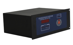
PRODUCT SHOW
Overvoltage
1 Overview
SAI -type arc harmonic elimination and over-voltage protection device is a computer controlled device 3 ~ 35kV neutral point indirectly grounded system arc harmonic elimination line selection and over-voltage protection device operating central monitoring unit is selected based on arc harmonic elimination control principle lines and over-voltage protection devices , the use of advanced , anti-interference ability PIC microcontroller as the core processing unit monitoring device .
This device uses a remote centralized control design, real-time monitoring arc harmonic elimination and over-voltage protection devices at the same time , according to the bus voltage upload to remote monitoring .
The device is installed locally design, with small size, light weight , good sealing, anti-interference ability , good seismic capacity , etc., suitable for use in harsh environments .
2 device function and protection configuration
This device provides the following protection and related functions:
Over 2.1 arc voltage detection and restrictions ;
2.2 resonance overvoltage detection and elimination ;
2.3 insulation monitoring ( zero-sequence voltage detector ) ;
2.4 voltage transformer (PT) high-voltage fuse fuse detection ;
2.5 voltage transformer (PT) secondary break detection ;
2.6 operating data display ;
2.7 Record date 16 event fault characteristic values ;
2.8 Record the data stored in FLASH memory , the device can be stored for more than three years Down ;
2.9 communication.
3 Technical Data
3.1 rated parameters : a working voltage :. AC220V/DC220V ( polarity requirement )
. b Frequency : 50Hz
3.2 Power:
a AC voltage circuit :. <0.2VA / phase (IN = 5A)
. b Current loop : <5W
3.3 Accuracy:
. a voltage measurement error of <5% ;
b. time measurement error of less than 20ms.
3.4 Environmental Conditions
3.8.1 The basic conditions:
. a Ambient temperature : 40 �� 5 ��
. b Relative humidity: 45% ~ 95%
c Atmospheric pressure :. 80 ~ 110Kpa ( 2km relative altitude and below ) .
3.5 Normal working conditions:
. a Ambient temperature : -20 �� ~ +50 ��
. b Relative humidity : Monthly average maximum relative humidity less than 95% , non-condensing surface casing .
c Working environment: No cause damage to the insulation of metal or corrosive gases and dust and mold more serious , no fire and explosion hazard substances .
3.6 Insulation:
3.6.1 Insulation resistance: conductive circuits were each charged between ground ( ie, housing or exposed non- current-carrying metal parts ) for using open circuit voltage of 500V test instruments measure the insulation resistance should not be less than 100M�� is .
3.6.2 Dielectric strength: conductive circuits were each charged between ground ( ie, housing or exposed non- current-carrying metal parts ) for , can withstand 50Hz, 2kV ( rms ) AC voltage test lasted 1min no breakdown or flash network phenomenon .
3.6.3 Each input , output energized conductive terminals respectively between the impact test , the AC circuit with a DC circuit , the circuit between the AC current and AC voltage circuits can withstand 5kV ( peak ) standard lightning .
3.7 Anti- electrical interference:
Can withstand a frequency of 1MHz and 100kHz oscillation damping ( first half-wave amplitude of the common mode voltage of 2.5kV, differential mode to 1kV) pulse interference test.
3.8 Mechanical properties:
a Working conditions : able to withstand the harsh response of �� grade level vibration , shock response test.
b transport conditions : able to withstand the harsh vibration level grade �� durable , durable and impact collision test.
4 unit structure
4.1 Structure Structure Size : 442 (w) �� 175 (H) �� 350 (L); Installation: embedded type .
Hole size 4.2
Fifth, the computer controller for use
5.1 LED Display Meaning
�� device power-up, immediate access to operational status , LED cycle PT secondary phase voltage UA, Ub, Uc. As shown below:
�� Fault LED device body last digit display E, the first shows A (b, c, o) for the corresponding input voltage circuit fault , the display 01 as the 1st line selection circuit malfunction. Such as:
�� LED display system resonance :
�� arc grounding system LED display ( for the fifth phase do A, b, C):
�� LED display system directly to ground ( line number 01 denotes the ground , with another fifth place for the A, b, C):
Resistance grounding system LED display ( line number 01 denotes the ground , with another fifth place for the A, b, C):
Voltage transformer fuse blown LED display ( for the fourth phase do A, b, C):
5.2 Key Operation
�� In the running state, press " Clock" button , you can view the time and on time .
( 1 ) for the first time by the "Clock " button , LED display year, month, day , press "��" or "��" button to move the date of adjustment , press the " OK" button to confirm the adjustment effective display y-good.
( 2 ) press the " Clock" button , LED display hours, minutes , seconds, press "��" or "��" button to adjust the time , press the " OK" button to confirm the adjustment effective display h-good.
�� In the running state, press " Settings" button to set the line selection circuit number and mailing address of the device.
( 1) The first time you press the "Settings" button , LED display OLC = 00, press "��" or "��" button to be selected wire loop adjustment , the factory default is 0 , press the " OK" button to confirm the adjustment effective display L-good.
( 2 ) press the " Settings" button , LED display A Add = 00, press "��" or "��" button to adjust the communication address , the factory default is 0 , press the " OK" button to confirm the adjustment effective display A-good.
�� In the running state, press " Search" button, you can view the fault history .
( 1 ) The first press displays : number ( 01 ) , the nature of the fault and fault phase , each subsequent press , followed by Display: occurrence date ( year, month , day ) , the occurrence of time ( hours, minutes , seconds ), A with maximum voltage ( peak ), B phase the maximum voltage ( peak ), C with maximum voltage ( peak ) .
( 2 ) the number "01 " for the last fault information, fault information displayed once finished , and then displays the previous ( 02 ) failure information .
( 3 ) when the fault message is not displayed , indicating no failure .
�� In isolation switch is in the OFF position , the controller is running , press the " test " button , can be single-phase high-voltage contactors points, closing test .
( 1 ) The first press the " test " button to display the "H-A", press " Confirm" to perform, display "A-H". Press the "OK " button , then the sub-gate , showing "A-F".
(2) B, C, D, E test with A.
�� stability arc grounding , press "��" key , crowbar action reset.
�� In a system failure , the device operated alarm , press the "��" key to disarm the alarm.
�� In debug mode, press "OK" and "Exit " button to clear the fault log.
�� In debug mode, press the "Exit " key to return immediately to run the state . In debug mode if no button five minutes , automatically returns to operation.
�� In debug mode, press the "reset" and "Confirm " button , the computer controller initializes devices , non-professional and technical personnel do not operate this .
A communication interface : RS485
2 , means of communication
�� Communication Format : Asynchronous , one start bit, eight data bits, one stop bit ;
�� Communication speed : 4800bps;
�� siting ways : by software settings , ranging from 00 to 99 , a total of 100 addresses ;
�� Communication: Monitoring host SAI-35 device uses one ( or many) from the main query .
3 , message format :
Addresses ( 8 ) the function code ( 8 ) a data area (8 �� n bits ) Checksum (L) Checksum (H)
Description : Address sub-station ; : Address
Function code : Command execution sub-function stations ;
Data area: address index downlink command when the master station commands to the uplink data ;
Check : CRC checksum mode .
4 , packet switching
�� ask switch
Send command system : Slave address 01 starting address ( 00 ) start address ( 00 ) switch number ( 00 ) switch number (28) CRC code (L) CRC code (H)
Device reply message : Slave address byte 01 reads ( 05 ) fault phase and fault type (BYTE1) fault line (BYTE2 BYTE3 BYTE4 BYTE5) CRC code (L) CRC code (H)
Meaning:
1) BYTE1 byte you : D0 = 1, A phase ; D1 = 1, B; Phase D2 = 1, C -phase ; D3 = 1, bus grounding ; D4 = 1, arc ground ; D5 = 1, metal grounding ; D6 = 1, the resistor to ground ; D7 = 1, resonance.
2 ) fault line byte you : BYTE2 bytes you : D0 = 1 ground Route 1 , D1 = the 12th line ground ......, BYTE3 byte D0 = 1 9 Line No. grounded , and so on .
�� asked analog
Issued under the system command: Machine No. 03 start address ( 00 ) start address ( 00 ) analog number ( 00 ) analog number (03) CRC code (L) CRC code (H)
Device reply message : the number of analog machine No. 03 ( 06 ) bytes BYTE1 (H) BYTE1 (L) BYTE2 (H) BYTE2 (L) BYTE3 (H) BYTE3 (L) CRC code (L) CRC code (H)
Significance : BYTE1, BYTE2, BYTE3, followed by : Ua, Ub, Uc.
