


PRODUCT SHOW
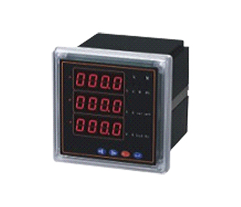
E-Multifunction Power Meter S4
One, overview
Multifunction power meter is a kind of intelligent electric meter with programmable measurement, display, digital communication and electric energy pulse output function, can complete the power measurement, power measurement, data display, data acquisition and transmission, and can be widely used in substation automation, distribution automation, intelligent building, internal energy measurement, management, appraisal; realize LED field display and remote RS-485 digital communication interface, using MODBUS-RTU communication protocol, with PC software different industry group Netcom hearing, user-friendly operation menu.
Two, the product specifications
The basic function of instrument type shape function
SAIE-AS4
SAIE-3S4
SAIE-9S4
SAIE-2S4
SAIE-4S4 three-phase voltage, three-phase current, active power reactive power without
Power frequency, power factor, power frequency, there is
Power wattless power LED digital tube display 72 x 72
80 x 80
96 x 96
120 x 120
144 x 1441 road 485 communication
2 two-way electric energy pulse output
Three, the technical parameters
Performance parameters
Transmission
Into the
Test
The amount of
Explicit
The network of three-phase three wire, three-phase four wire
Voltage rating of AC100V, 220V, 380V (please specify)
A load duration: 1.2 times: 10 times /10s instantaneous
Power <1VA (per phase)
Impedance >500k
The accuracy of RMS measurement, accuracy class 0.5
Current ratings, AC1A, 5A (please specify)
A load duration: 1.2 times: 2 times /10s instantaneous
Power <0.4VA (per phase)
Impedance <2m
The accuracy of RMS measurement, accuracy class 0.5
The frequency of 40 ~ 60Hz, the accuracy of 0.1Hz
Power apparent power, active precision of 0.5 grade, 1.5 grade precision without power
Four of the electrical energy measurement accuracy class 1 quadrant, active, inactive accuracy class 2
Range: 0 ~ 999999.99 of total
Display programmable, switching, circulation (LED) display
The power supply operating range of AC/DC85~265V
Power ≤ 5VA
Digital output interface RS-485, MODBUS-RTU protocol
Pulse output 2 way electric energy pulse output
Environment and working environment of -25 ~ 70 ℃
-20 ~ 55 ℃ storage environment
Safety voltage input and power >2kV, input and output >2kV, power supply and output >1kV
The input, output, power on the insulation shell of >50M
Four, the installation guide
The 4.1. shape and size of mounting hole
Instrument appearance size hole size
Unit: mm wide high deep Width High
72 square 74741056767
80 square 84841057676
96 square 9696959191
42 square 12012095107107
144 square 14414483133133
4.2. instrument and hole diagram:
The 4.3 wiring schematics and terminal diagram:
4.3.1 terminal diagram:
Schematic diagram of the 4.3.2 junction:
Note: the symbol "*" represents the current incoming line terminal, the terminal is for reference only, the specific kind
In 4.4, the matters needing attention:
4.1.1. auxiliary power supply
Multifunction power meter auxiliary power switching power supply, if not for the special statement, with the AC/DC85~265V power supply interface, ensure that the power supply provides for the series of products, in order to prevent damage to the product. (DC power supply is "1", "2" is negative)
①, recommended to install the 1A fuse in power line.
Second, for the power quality is poor, recommended to install surge suppressor and fast pulse suppressing device in the power supply circuit.
4.4.2. signal input
Calculation by each measurement channel separate collection, ensure the use of the same, symmetry, which has various connection mode, suitable for different forms of load.
①, voltage input: input voltage should be less than the rated input voltage products 120%, otherwise it should consider using the PT; installation 1A fuse in the input voltage;
Second, the current input: input current should be less than the rated input current products (1A, 5A) 120%, you should use an external CT;
If the use of the CT is connected with other instruments, wiring should be used in tandem;
Recommend the use of wiring row, not directly connected with CT, in order to assemble; prior to the removal of the current input line of products, we must first disconnect the CT a circuit or short circuit two times.
Third, to ensure that the input voltage, current, phase sequence and wiring diagram consistency, direction should be consistent, otherwise it will numerical and symbolic power, electric energy error!
Connection mode, the instrument outside, to be consistent with the internal network settings, three line three line NET=N.3.3; three-phase four wire NET=N.3.4. Set the inconsistent cause a voltage or power is not correct.
The 4.4.3 notes:
①, communication connection is recommended to use three core shielding wire, each core cross section is not less than 0.5mm2, are respectively connected with the A, B, grounding, shielding layer of the ground, wiring should enable the communication line from the power cable or other strong electric field environment.
In the end, suggest that A, B and instrument matching resistance, resistance range is 120 ~ 10K Ω (according to the bus connection to the instrument number of different resistance range similarities and differences, the general 32 the following instruments incorporated with 120 Ω resistor is bette
Five, the programming and the use of
5.1 key definitions
Enter password: enter the confirmation and digital parameters confirmation.
The menu key: used to exit a function and return to the previous menu, select the function menu interface.
Right: measurement display when doing conversion function, when the data is modified this key for digital keying (from 0-9999)
The left arrow: measurements show that when doing conversion function, when the data is modified this key to do digital subtraction key (from 0-9999)
5.2 measurement display:
Multifunction power meter can be electric parameters measurement in power system are: Ua, Ub, Uc, Uab, Ubc (voltage), Uca (line voltage) Ia, Ib, Ic (current); Pp (total active power); Qp (total wattless power (PFs)
